No products in the cart.

10MHZ DDS FUNCTION GENERATOR
$2106.00
10MHZ DDS FUNCTION GENERATOR
NORMAL DELIVERY 1-2 weekCall us to get the exact delivery date.
International Credit cards are not accepted on online orders.
Brand:Fluke
 Warranty: As per Manufacturer policy
 100% Genuine Product Brand Warranty
 Easy and Secure Payment


Timely delivery with complete tracking
271-U 115V – Fluke 10Mhz Dds Function Generator (2423224) The 271 is a high performance function generator using Direct Digital Synthesis techniques. A wide variety of standard waveforms are provided and an arbitrary waveform capability allows it to be used to generate non-standard and user-defined waveforms. Extensive modulation capabilities make this a highly versatile signal source. High performance function generator
The 271 is a high performance function generator using Direct Digital Synthesis techniques. A wide variety of standard waveforms are provided and an arbitrary waveform capability allows it to be used to generate non-standard and user-defined waveforms. Extensive modulation capabilities make this a highly versatile signal source. Waveforms Direct digital synthesis for accuracy and stability The DDS generator offers not only exceptional accuracy and stability but also high spectral purity, low phase noise and excellent frequency agility. A wide range of waveforms Arbitrary waveform capability Up to five arbitrary waveforms of 1024 10-bit words can be stored in non-volatile memory. The waveform clock is 27.48 MHz maximum. This facility considerably expands the versatility of the 271, making it suitable for the generation of highly complex waveform patterns. In addition, the 271 offers numerous �complex waveforms pre-defined in ROM. These include commonly used wave shapes such as sine x/x, decaying sinewave, and exponential rise and fall. Locked generators Powerful modulation modes Two sweep markers are provided, which are adjustable while sweep is running. The markers can provide a visual indication of frequency points on an oscilloscope or chart recorder. AM. Amplitude modulation is available for all waveforms and is variable in 1 % steps, up to 100 %. Trigger/Burst. All waveforms are available as a triggered burst, whereby each positive edge of the trigger signal will produce one burst of the carrier, starting and stopping at the phase angle specified by the start-stop phase setting. The number of cycles in the burst can be set between 0.5 and 1023. Gated. The gated mode turns the output signal on when the gating signal is high and off when it is low. Both triggered and gated modes can be operated from the internal trigger generator (0.005 Hz to 50 kHz) or from an external source (dc to 1 MHz). Waveform hop. The generator can be set up to ‘hop’ between a number of different waveform setups, either at a pre-determined rate or in response to a manual or bus trigger. Up to 16 different hop waveforms can be defined in terms of frequency, amplitude, function, offset and duration, which is variable in 1 ms steps up to 60 seconds. |
Specification
| Waveforms | |||||||||||
| Frequency |
| ||||||||||
| Sinewave |
| ||||||||||
| Squarewave |
| ||||||||||
| Triangle |
| ||||||||||
| Positive and Negative Ramp |
| ||||||||||
| Positive and Negative Pulse |
| ||||||||||
| Multi-Level Squarewave |
| ||||||||||
| Arbitrary (and complex) |
| ||||||||||
| Symmetry |
| ||||||||||
| Main Output | |
| Output impedance | 50 ? or 600 ? switchable |
| Amplitude | 5 mV to 20 V pk-pk open circuit (2.5 mV to 10 V into 50 ?/600 ?). Output can be specified as V-H: 2(open circuit value) or V (Voltage into the characteristic impedance) in pk-pk, RMS or dBm. Note that in positive or negative pulse modes the amplitude range is 2.5 mV to 10 V pk-pk O/C. |
| Accuracy | Typically ±3 % ±1 mV at 1 kHz into 50 ?/600 ? |
| Flatness | ±0.2 dB to 500 kHz; ±1 dB to 10 MHz |
| Pulse aberrations | <5 %+ 2 mV |
| DC offset | ± 10 V from 50?/600 ? offset plus signal peak limited to ± 10 V from 50 ?/600 ? |
| Resolution | 3 digits or 1 mV for both amplitude and offset |
| Modulation | |||||||||||
| Amplitude Modulation |
| ||||||||||
| Frequency Shift Keying (FSK) |
| ||||||||||
| Operating Modes | |||||||||||||
| Trigger/burst |
| ||||||||||||
| Gated |
| ||||||||||||
| Sweep |
| ||||||||||||
| Hop |
| ||||||||||||
| Start/Stop Phase |
| ||||||||||||
| Trigger Generator | Internal source 0.005 Hz to 50 kHz squarewave adjustable in 20 us steps. 3 digit resolution. Available for external use from TRIG/SWEEP OUT socket. | ||||||||||||
| Auxiliary Outputs | |
| Aux Out | CMOS/TTL levels with symmetry and frequency of main output and phase of start-stop phase setting |
| Trig/Sweep Out | Multi-function output depending upon mode. Except in sweep mode, the output is that of the trigger generator at CMOS/TTL levels from 1 kW.In Sweep mode the output is a 3-level waveform, changing from high (+4 V) to low (0 V) at the start of sweep, with narrow 1 V pulses at each marker point. |
| Inputs | |||||||
| Ext Trig |
| ||||||
| VCA In |
| ||||||
| Phase Locking | |
| Clock in/out | TTL/CMOS threshold levels; output impedance typically 50 ? as an output |
| Sync out | TTL/CMOS logic levels from typically 50 ?. The signals from these sockets are used to phase lock two or more generators. |
| Interfaces | |
| RS-232 | Variable Baud rate, 9600 Baud maximum. 9-pin D-connector. |
| IEEE-488 | Conforming with IEEE488.1 and IEEE488.2 |
| General Specifications | |
| Display | 20 character x 4 row alphanumeric LCD |
| Data entry | Keyboard selection of mode, waveform etc.; value entry direct by numeric keys or by rotary control. |
| Stored settings | Up to 9 complete instrument set-ups may be stored and recalled from battery-backed memory. |
| Size | 3U (130 mm) height; half-rack (212 mm) width, 330 mm long |
| Weight | 4.1 kg (9 lb) |
| Power | 100 V ac, 110 to 120 V ac or 220 to 240 V ac +/- 10 %, 50/60 Hz ac by internal adjustment; 30 VA max. |
| Operating range | +5 ?C to 40 ?C, 20 to 80 % RH |
| Storage range | -20 ?C to +60 ?C |
| Options | IEEE-488 interface; 19-in rack mounting kit |
| Weight | 1 kg |
|---|
Reviews
There are no reviews yet.
Related products

Accessories
$1280.00
SKU: 5627A-BEND-BManufacturer: Fluke


SKU: EM3782-96-6#
Manufacturer: Fluke
Manufacturer: Fluke
SKU: EM1383-C-36#
Manufacturer: Fluke
Manufacturer: Fluke
Accessories
$14882.00
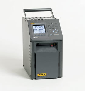
SKU: 9173-E-R-156Manufacturer: Fluke
$4755.00
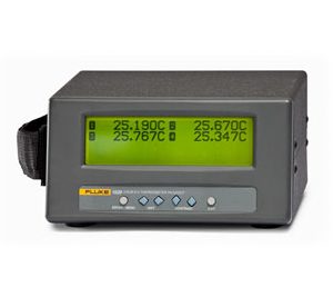
SKU: 1529Manufacturer: Fluke
$7223.37
SKU: AXTAP1210BT-BT/SFPManufacturer: Fluke


Be the first to review “10MHZ DDS FUNCTION GENERATOR”