No products in the cart.
Our BestSellersBrowse All
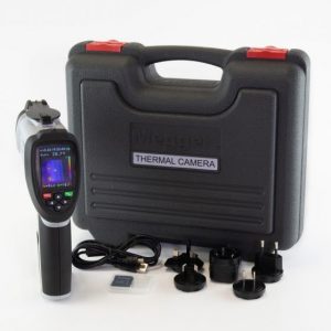

$2160.00
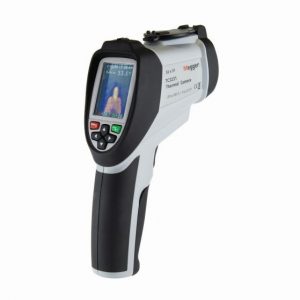
SKU: 514360-8Manufacturer: Megger
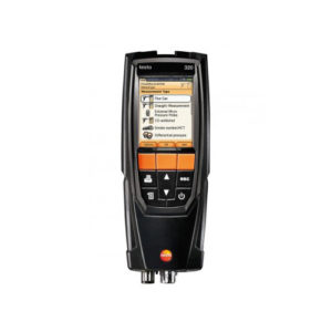
Combustion / Flue Gas Analyzers
$1857.30
SKU: 0563 3220 70Manufacturer: Testo
Minimum Required Order Value - $200 | We do not ship to residential address


Combustion / Flue Gas Analyzers
Omni Controls is your resource for test and measurement equipment. We only work with the world class brands you love and trust. OMNI Controls is making it easier than ever to meet your equipment needs with our online store. Browse through thousands of products in a variety of ways to ensure that you find exactly what your looking for at exactly the right price.

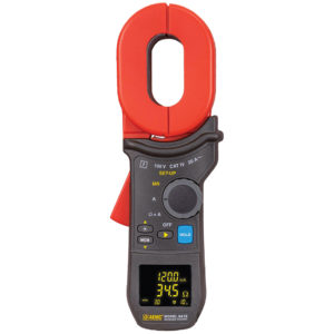
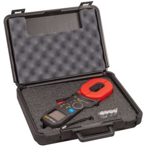
Earth & Ground Resistance Testers
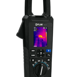
Thermal Imagers


‘We sell to B2B only, we do not ship to residential accounts. Enter your business address’