No products in the cart.
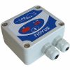

Novus Automation myPCLab, USB Data logger
$199.00
myPCLab is a very compact Data Acquisition tool that connects to a PC via a USB port and monitors two universal input
analog variables along with one digital input. From hobbyists to scientists, from simple technical tasks to complex
engineering activities, myPCLab can be an invaluable tool for on-line monitoring and data logging in school, laboratory
research, machine data recording, and industrial understanding.
It comes with intuitive and easy-to-use Windows software which plots and records data, shows gauges, bar graphs and
digital readouts. The USB port is accessed as a virtual serial port, which makes myPCLab compatible with SCADA
software with Modbus RTU driver or with any program with ASCII serial communication.
Multiple units of myPCLab can be connected to the same computer, easily expanding the number of inputs. The
myPCLab software can simultaneously communicate with multiple modules.
This manual describes software installation and connection of input signals to a myPCLab module. Instructions on using
the software are available on its help system.
NORMAL DELIVERY 1-2 week
Call us to get the exact delivery date.
International Credit cards are not accepted on online orders.
Brand:Novus Automation
 Warranty: As per Manufacturer policy
 100% Genuine Product Brand Warranty
 Easy and Secure Payment


Timely delivery with complete tracking
SPECIFICATIONS
Analog Input Signals: Configurable for channels 1 and 2. The input signals and measuring ranges are listed in the
following table.
• Thermocouples: J, K, T, E, N, R, S and B types.
Input Impedance >> 1 MΩ
• Pt100: Three wires connection, 625 µA bias current, α = 0.00385.
• Linear Signals: 0 to 50 mVdc: Input Impedance >> 1 MΩ
0 to 10 Vdc: Input Impedance = 1 MΩ. Available only in channel 1.
4 to 20 mAdc: Input Impedance: 22 Ω (+ 2,0 Vdc)
Input Type Maximum Range
J Thermocouple -130,0 to 940,0 °C (-202,0 to 1724,0 ºF)
K Thermocouple -200,0 to 1370,0 °C (-328,0 to 2498,0 ºF)
T Thermocouple -200,0 to 400,0 °C (-328,0 to 752,0 ºF)
E Thermocouple -100,0 to 720,0 °C (-148,0 to 1328,0 ºF)
N Thermocouple -200,0 to 1300,0 °C (-328,0 to 2372,0 ºF)
R Thermocouple 0,0 to 1760,0 °C (-32,0 to 3200,0 ºF)
S Thermocouple 0,0 to 1760,0 °C (-32,0 to 3200,0 ºF)
B Thermocouple 500,0 to 1800,0 °C (932,0 to 3272,0 ºF)
Pt100 RTD -200,0 to 650,0 °C (-328,0 to 1202,0 ºF)
0 to 50 mVdc Adjustable from -32767 to +32767
0 to 10 Vdc (Channel 1) Adjustable from -32767 to +32767
4 to 20 mAdc Adjustable from -32767 to +32767
myPCLab module sensors and signals
Digital Input: Logic voltage or dry contact signals.
“0” Logic Level: contact closed or voltage lower than 0.5 Vdc.
“1” Logic Level: contact opened or voltage from 2.0 V to 5,0 Vdc.
Digital input special features: Digital input can be configured for counting, timing or frequency measuring (pulses per
time unit). Configurable: debounce time and scale factor.
Counting: It counts from 0 up to 4294967295. It is selectable to count on input rising edge, falling edge or
both. Maximum input frequency: 1 kHz (square wave, no debounce).
Timing: It times up to 4294967295 miliseconds (more than 49 days). It is selectable to run timing when
input in logic level “0” or when in “1”. Accuracy: 0.5 % of the indicated time.
Frequency: It counts the number of pulses (rising edge, falling edge or both) in each base time,
configurable from 1 to 65535 seconds (18 hours). Maximum input frequency: 500 Hz (square wave, no
debounce). Maximum input frequency: 500 Hz (square wave, no debounce). Accuracy: 0.5 %.
Ambient Temperature Sensor: Internal thermistor.
Total Accuracy: Thermocouples R, S and B: 0.25% of the maximum range ± 3 °C (with maximum A/D resolution);
Other thermocouples: 0.25% of the maximum range ± 1 °C (with maximum A/D resolution);
Pt100, voltage and current: 0.20% of the maximum range (with maximum A/D resolution);
Ambient temperature channel: ± 1.5 °C (after 20 minutes connected to the USB port).
A/D Resolution: Configurable from 15 to 11 bits.
Input Sampling Rate: From 8 to 128 samples per second, depending on configured A/D resolution and number of
enabled channels.
Computer Interface: USB V1. 1 Plug and Play, virtual serial port interface.
USB connection: Mini-B receptacle.
Power supply: From the USB bus. Typical current 30 mA.
Operating environment: 0 to 50°C, 10 to 90% relative humidity, non-condensing.
Electromagnetic Compatibility: EN 50081-2, EN 50082-2.
Built-in cold junction compensation for thermocouples and wire resistance for Pt100.
ABS case, dimensions: 70 x 60 x 18 mm. See figure.
CONNECTIONS
This module operates only when connected to a PC USB bus, using the included type-A to mini-B cable. The following
figure shows all possible input connections.
Pt100 WIRING
Connections of channel 1 are on terminals 6, 7 and 8. For channel 2 on terminals 2, 3 and 4.
Connection with 3 wires from the sensor element to the module is necessary to cancel the
cable resistance error in the measurement. The 3 wires must have the same length and
gauge.
To connect a Pt100 with 2 wires, connect terminals 7 and 8 (channel 1) or 3 and 4 (channel
THERMOCOUPLE WIRING
Connections of channel 1 are on terminals 6 and 7. For channel 2 on terminals 2 and 3.
Observe indicated polarity.
Cables for thermocouple connection must have the same thermo-electrical characteristics of
the thermocouple element (compensation or extension cable). Observe that both the
thermocouple and the compensation cable must be connected with correct polarity.
If compensation cable is not used or is not connected with the correct polarity, large
measurement errors will arise.
4-20 mA WIRING
Connections of channel 1 are on terminals 6 and 7. For channel 2 on terminals 2 and 3.
Observe indicated polarity.
0-50 mV WIRING
Connections of channel 1 are on terminals 6 and 7. For channel 2 on terminals 2 and 3.
Observe indicated polarity.
0-10 V WIRING
Linear voltage signals from 0 to 10 V can only be connected to channel 1, terminals 5 and 6.
Observe indicated polarity.
DRY CONTACT DIGITAL INPUT WIRING
Digital signals are connected to channel 3, terminals 1 and 2.
The contact connected to digital input must not have any electrical voltage.
VOLTAGE DIGITAL INPUT WIRING
Digital signals are connected to channel 3, terminals 1 and 2. Observe indicated polarity.
Voltage levels applied to this channel must be within the specified limits. See “Specifications”.
| Weight | 1 kg |
|---|
Related products
Other Test Meters & Detectors
Novus Automation 8812130000 FieldLogger USB, 512K Logs, RS485, data logger
$1022.00
SKU: 8812130000Manufacturer: Novus Automation
Other Test Meters & Detectors
Novus Automation 8800180040 HUBA 528 Absolute pressure, 4-20mA out IP65 connec. 0-4 bar (0-58 psi)
$621.00
SKU: 8800180040Manufacturer: Novus Automation
$363.00
SKU: 81100H0224Manufacturer: Novus Automation
Other Test Meters & Detectors
Novus Automation 8120200520 N1200-HBD RS485 USB Process Control. heater break detector 1/16 DIN
$289.00
SKU: 8120200520Manufacturer: Novus Automation
Other Test Meters & Detectors
$248.00
SKU: 8804111001Manufacturer: Novus Automation

Other Test Meters & Detectors
Upgrade SuperView SCADA Software, License 3 remote clients (Hardkey)
$566.00
SKU: 8845000063Manufacturer: Novus Automation
Other Test Meters & Detectors
J-type thermocouple, 8x7mm, big bayonet spring, 3 m FFM cable, 0-300C
$53.00
SKU: 8830015830Manufacturer: Novus Automation
Other Test Meters & Detectors
NP400 Ceramic sensor, 1/2 NPT, DIN, IP65, 4-20MA, 0-5 bar (72.5 Psi)
$90.00
SKU: 8801512005Manufacturer: Novus Automation
$228.00
SKU: 8803696410Manufacturer: Novus Automation
Other Test Meters & Detectors
$105.00
SKU: 8801522010Manufacturer: Novus Automation