No products in the cart.

DC to DC transmitter
$399.00
DC to DC transmitter, factory ranged I/O
NORMAL DELIVERY 1-2 weekCall us to get the exact delivery date.
International Credit cards are not accepted on online orders.
Brand:API
 Warranty: As per Manufacturer policy
 100% Genuine Product Brand Warranty
 Easy and Secure Payment


Timely delivery with complete tracking
| Features | |
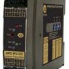
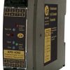
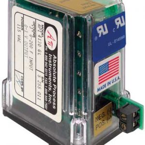
| The API 4300 G accepts a DC voltage or current input and provides an optical- | |
| ly isolated DC voltage or current output that is linearly related to the input. | |
| Typical applications include signal isolation, conversion, boosting or a combina- | |
| tion of the three. Full 3-way isolation (input, output, power) makes this module | |
| useful for ground loop elimination, common mode signal rejection or noise pick- | |
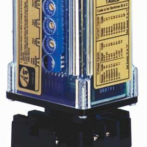
| The API 4300 G is factory configured to customer requirements. Common | |
| ranges as well as custom ranges are possible. Consult the factory for assis- | |
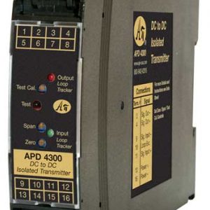
| API exclusive features include two LoopTracker LEDs and a Functional Test | |
| Pushbutton. The LoopTracker LEDs (Green for input, Red for output) vary in | |
| DC toDC Isolated Transmitter | |
| Input: | 0-100 mV to 0-500 VDC, Bipolar Voltages, 0-1 mA to 0-900 mADC |
| Output: | 0-1 V to ±10 VDC or 0-1 mA to 4-20 mA |
| ● Full 2000 V Input/Output/Power Isolation | |
| ● Factory Set Custom Input and Output Ranges | |
| ● Input and Output LoopTracker® LEDs | |
| ● Functional Test Pushbutton | |
| ● Built-In Loop Power Supply | |
| ■ Convert, Boost, Rescale Process Signals | |
| ■ Interface Process Signals with Panel Meters, Recorders, Data | |
| Acquisition Cards, PLCs, DCS Systems, SCADA Systems | |
| Specifications | |
| Input Ranges | |
| Factory ConfiguredPlease specify output range or consult factory | |
| See table on other side for common ranges | |
| Minimum | |
| Voltage: | 0-100 mVDC |
| Bipolar Voltage: | ±100 mVDC |
| Current: | 0-1 mADC |
| System voltages must not exceed socket voltage rating | |
| Input Impedance (Voltage) | |
| 200 kΩ minimum | |
| Input Voltage Burden (Current) | |
| 1.25 VDC maximum | |
| Output Zero and Span | |
| Multiturn potentiometers to compensate for load and lead variations | |
| ±15% of span adjustment range typical | |
| Input Loop Power Supply | |
| 18 VDC nom., unregulated, 25 mADC, max. ripple, less than 1.5 Vp-p | |
| LoopTracker | |
| Variable brightness LEDs indicate input/output loop level and status | |
| Output Ranges | intensity with changes in the process input and output signals. Monitoring the |
| state of these LEDs can provide a quick visual picture of your process loop at | |
| Factory ConfiguredPlease specify output range or consult factory | |
| all times. The functional test pushbutton provides a fixed output (independent of | |
| Minimum | |
| Voltage: | 0-1 VDC |
| Bipolar Voltage: | ±1 VDC |
| Current (20 V compliance): | 0-1 mADC |
| Output Linearity | |
| Better than ±0.1% of span | |
| Output Ripple and Noise | |
| Less than 10 mVRMS | |
| Functional Test Button | |
| Response Time | |
| 70 milliseconds typical | |
| Common Mode Rejection | |
| 120 dB minimum | |
| Isolation | |
| 2000 VRMS minimum | |
| Ambient Temperature Range and Stability | |
| -10°C to +60°C operating ambient | |
| Better than ±0.04% of span per °C stability | |
| Power | |
| Standard: | 115 VAC ±10%, 50/60 Hz, 2.5 W max. |
| P | |
| A230 option: | 230 VAC ±10%, 50/60 Hz, 2.5 W max. |
| D option: | 9-30 VDC, 2.5 W typical |
| Weight | 1 kg |
|---|
Reviews
There are no reviews yet.
Related products


$529.00
SKU: DPG2000BBL-D4Manufacturer: API
Other Test Meters & Detectors
APD 4420 D DC to DC math, A/B. Fully isolated. Inputs share common ground.
$559.00
SKU: APD 4420 DManufacturer: API
Other Test Meters & Detectors
APD 3200 D M420 Valve positioner, milliamp feedback. Isolated input.
$369.00
SKU: APD 3200 D M420Manufacturer: API
Other Test Meters & Detectors
APD 4401 D DC to DC math, (A+B+C)/3. Fully isolated. Inputs share common ground.
$559.00
SKU: APD 4401 DManufacturer: API
Login
Register
Loading...
Be the first to review “DC to DC transmitter”